Pages

Gingery Shaper - Column Front

The Column Front casting was next.  I machined up the pattern in two pieces and located them to each other using some cut-off nails.  The bottom piece has the runners and gates included on it to keep the two pieces of the pattern located to each other.


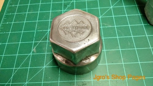
Here is the casting along with some other parts that I made that day.

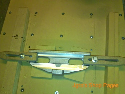
The casting got machined up on my CNC (sorry, forgot to take pictures).  The next step was to attach the Vertical Slide Way and attach it to the sides.

Locating the ways
Screws added

Setting up to attach the sides to the Column Front. 

After the Column Front was attached, I made the top rear spreader and installed it and added the spreader bolt on the bottom.

I then took the assembly to where I work and mounted it on a mill and milled the top of the assembly to make both sides level and then milled the shelves that the ram ways will slide on.


Gingery Shaper - The Beginning


I've started making the Gingery shaper.  The first step was to model it up in CAD so I can see how everything goes together and to have models to cut patterns on the CNC.  Here's the model so far.  It's not completely finished, but enough to get started.  The only change to the design from the book was that I went with a 3/8" thick plate on the ram as opposed to the 1/4" thick plate that Gingery describes.


The first part to make was the column side.  Here is the pattern:


I had my name engraved into the pattern, but it didn't cut too well in the MDF, so I filled it in.  I have one pattern with the name and one without.  Here is one of the castings.  This one has the name on it.


The one in the background is scrap.  I used some new greensand and the surface finish was horrible.

I then set them up in the CNC and controlled it manually to rough machine the castings.


Grease Caps

I finally got the grease caps done and installed on the truck.  They turned out pretty good.


Grease Caps - Machining

To machine up the castings, first I had to do some things. I needed something to hold the bit. I had made a boring bar for boring out the headstock and tail stock for the Gingery lathe, so I modified that to fit into my lantern post. Then I had to grind up a bit.

I bored out the inside to the ID of the thread and cut a relief at the back of the thread. I also cut a small section at the beginning of the thread that was the OD of the thread. I then spent 4 hours on Sunday trying to figure out the change gears. I had to make a couple of bushings to get everything to work.

I set up my newly made indicator holder so that when the bit was in the middle of the relief at the back of the thread, the needle was at zero. I probably didn't need it, I could hear when it stopped cutting, but I wanted some extra insurance.

I had watched some videos on Youtube to get the setup and order of operations down. The actual cutting was pretty simple. I kept adjusting the compound slide feed with each pass until it just touched the OD that I had machined at the beginning of the thread. Now I have to change the change gears back so I can cut the OD of the part. I wanted to cut a male thread gauge, but I didn't have any stock around. After I cut the OD of the part, I tried it on the truck and see how good a job I did.


It fit!

After I verified that it worked, I did a quick polish job. It's not perfect, but this was a practice piece.


Grease Caps

 My next project is to make grease caps for the wheels of the fire truck. We only have 2 and one of them looks like they pumped too much grease into it at one time and deformed it. The original is an aluminum stamping, but since I haven't been able to find any, I want to cast it.

Here are the originals.

I decided to go the Bondo route to add draft and material thickness. After I got all of the paint off and everything degreased, I slapped some bondo on the inside. I then taped off the end and chucked it in the lathe and turned it on slow.  The theory was that centrifugal force would force the bondo to the outside of the part. It kinda worked. It got a little thick on one side and the other side didn't have enough.
It took a few applications of Bondo to get enough on to machine away. I put about 3 degrees draft on both the inside and out side.


Here are the castings.  They turned out pretty good. One has a flaw in it. I'll use that one first to test out the thread cutting on the lathe. I know I'll probably screw it up since I haven't cut threads in over 20 years.


This one has the flaw.  The other one turned out good.

Next.....machining

Gingery Lathe Upgrades

I made some upgrades to my Gingery Lathe.  First thing I had to change was the tail stock.  When I bored it out, I did not get a good bore all the way through the tail stock.  This ended up with the tail stock ram being tight in one part and loose in the others.  When I would clamp it down with the set screw, the ram would get put out of alignment.  I started by purchasing a grinding wheel (on sale at Menards for $25.00) and grinding a new cutting bit.  I bored the tail stock until it had a nice consistent bore all the way through.  It ended up at .783" diameter.  I then made a new ram on the Craftsman lathe.  I turned it until it was .001" oversize and sanded with emery cloth until it would slide through with a little bit of force.  I then remade the rear cap and tail stock screw.  It works real well now.  No play anywhere.


As long as I had the lathe torn apart, I added some more screws to hold down the bed ways.  I added 8 flat head cap screws in between the existing bed screws.  This stiffened up the ways tremendously.  When I put a test piece between centers to check for run-out, I put an indicator on the tail stock ram.  There was no movement at all when turning.  I used to be able to see the tail stock move when turning out-of-round stock.  I actually got the best surface finish in steel that I've ever gotten. 


The last thing I did was to turn the outside face of the carriage wheel and stamp numbers on it.  It is much easier to read now.


Craftsman Lathe

My dad, after having it for about 40 years, gave me his lathe (he's 79 now). It's a Craftsman 6" lathe, model #101.07034 from the 40's-50's. It's complete with back gears, face-plate, 3-jaw chuck, 4-jaw chuck, steady rest and many accessories. I'll do some clean-up on it and put it to work. This was my dad's baby, so I know it was well taken care of. Thanks dad!


Table Saw Fence Part 2

Made some more progress today. First I cut off the sprues and runners and then set it up on my CNC for machining. This is after the first cuts.


I had to move the part to make the second cut because the clamps were in the way.  You can see a little bit of shrink in the center, but it will not change how the part functions, so I didn't worry about it.


I then flipped the part and machined off the base where the 8020 will get fastened to.


I drilled and tapped the base for the button head screws that will hold down the 8020 and one more for the clamp screw. I also drilled some access holes thru the 8020 for tightening/adjusting the fence.


The knob is attached to a piece of 1/4-20 threaded rod and goes thru the tapped hole in the base and into a piece of plastic that rides along the underside of the angle iron.


I added a rail along the back of the table and cut a piece of delrin to keep the fence sitting a little above the tabletop so it doesn't scrape the surface.


Next step is making an outfeed table.